3 RobotZero Modules Description
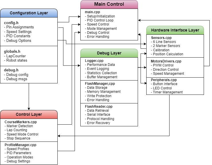
As shown in Figure 1, RobotZero’s architecture is organized into distinct layers, each responsible for specific aspects of the robot’s operation.

Let’s examine each module and its key features:
3.1 Configuration Layer
3.1.1 config.h
The configuration hub of the system, this module defines all crucial parameters including pin assignments, speed settings, and control constants. A notable feature is its use of conditional compilation (#if DEBUG_LEVEL > 0) to ensure zero overhead in normal operation mode, demonstrating our commitment to efficiency.
3.1.2 globals.h
Manages global state variables that need to be accessed across different modules. While global variables are generally discouraged, here they serve a crucial role in maintaining real-time performance by avoiding function call overhead for frequently accessed states.
3.1.3 debug.h
Implements a debug message system that stores strings in Flash memory instead of RAM, using PROGMEM for optimal memory usage. This approach ensures that debug capabilities don’t impact the robot’s limited RAM resources.
3.2 Hardware Interface Layer
3.2.1 Sensors
Manages six line sensors and two marker sensors through a calibration-based approach. The unique feature here is the weighted average calculation that provides precise positional data. The system maintains both raw and processed values, enabling real-time adjustments while preserving original readings for analysis.
3.2.2 MotorsDrivers
Implements motor control using PWM, with a key feature being its ability to handle both forward and reverse motion through a single interface. The module includes built-in protection against invalid PWM values, ensuring safe operation even under software errors.
3.2.3 Peripherals
Handles external interfaces including button input and LED status indication. Notable is its debounce implementation that maintains responsiveness while ensuring reliable button detection, essential for both operation and calibration phases.
3.3 Control Layer
4 CourseMarkers
The CourseMarkers class manages track feature detection and the robot’s behaviour responses. A key innovation is its time-controlled marker detection system, using a fixed interval (MARKER_READ_INTERVAL) to optimize sensor readings. The class implements an efficient state machine that processes four distinct states (0-3) representing different marker combinations. Its detection system includes timing controls to ensure reliable operation while minimizing processing overhead.
4.0.1 ProfileManager
Manages different operation profiles (analysis and speed modes). The key innovation here is its transparent speed value translation system, which allows the same base code to operate under different performance parameters without modification.
4.1 Debug Layer
4.1.1 Logger
Implements a logging system using circular buffers to maintain performance. A key feature is its ability to write to flash memory only during straight-line sections, ensuring logging doesn’t interfere with critical control operations.
4.1.2 FlashManager
Handles flash memory operations with built-in error checking and recovery mechanisms. Notable is its page-aligned writing system that maximizes flash memory lifespan while ensuring data integrity.
4.1.3 FlashReader
Manages data retrieval through a structured protocol, including checksums for data validation. The module implements a multi-marker system to ensure reliable data transmission even under noisy serial connections.
4.2 Main Control
4.2.1 main.cpp
The core control loop implementing PID-based line following. A significant feature is its non-blocking setup sequence that maintains system responsiveness during initialization and calibration. The module seamlessly integrates debug features when compiled with DEBUG_LEVEL > 0 while maintaining optimal performance in normal operation.